HYGROSHELL
//date_ october 2023
//location_ chicago architecture biennial, Chicago/US
//team_ ITECH Class 21/22, ICD & ITKE University of Stuttgart
//methods_ 7-axis robotic milling, self-shaping
//paper_ *link to paper
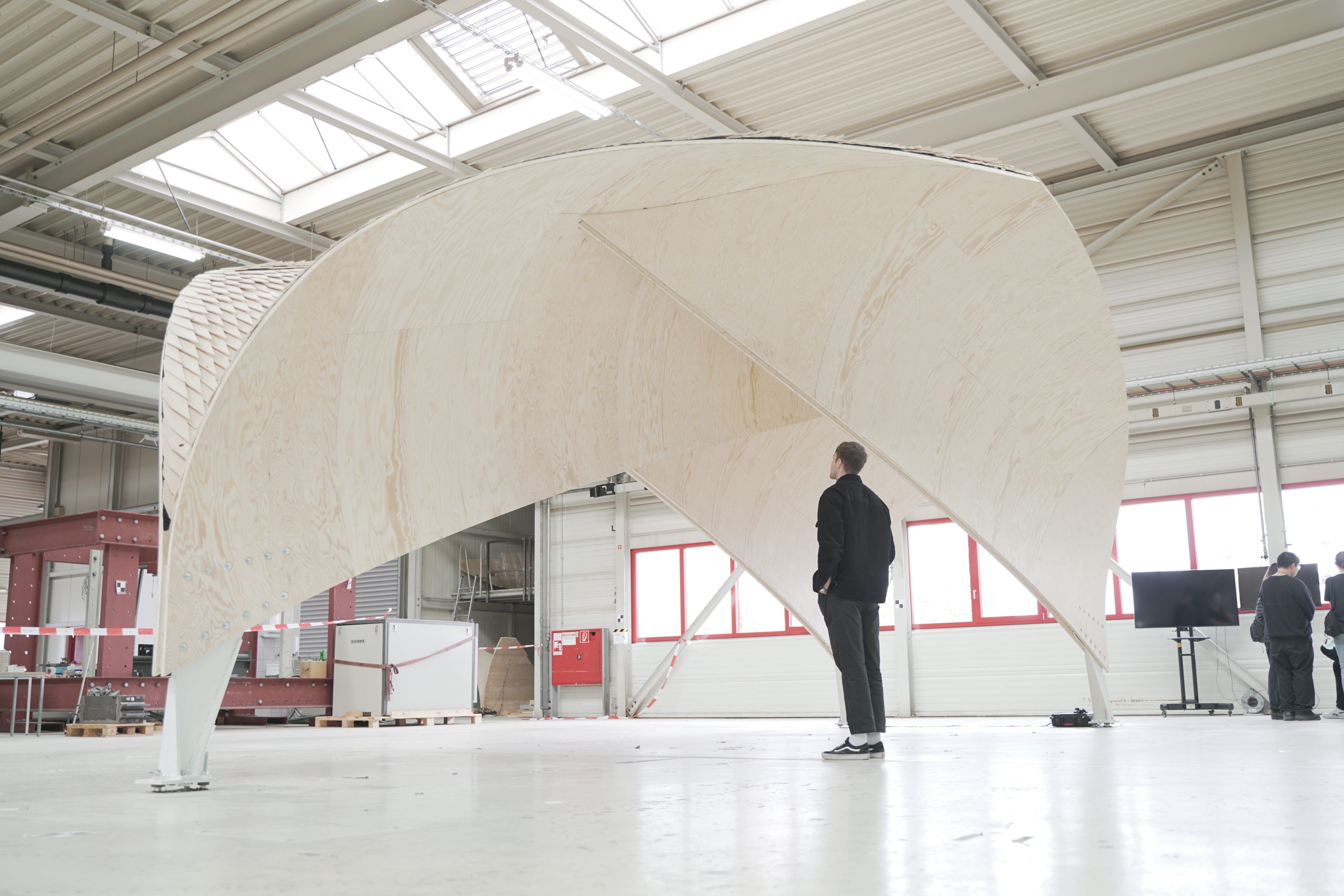
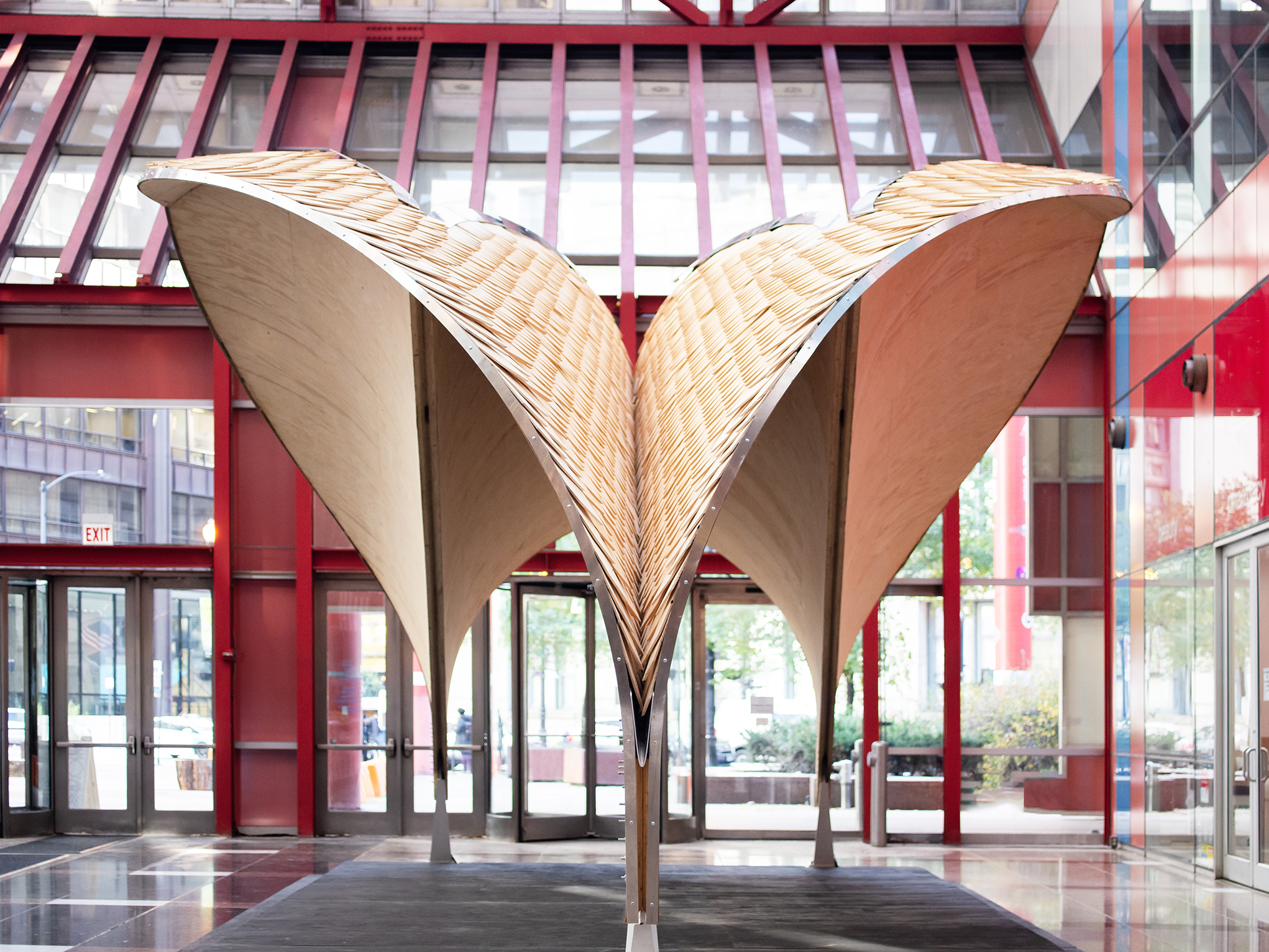
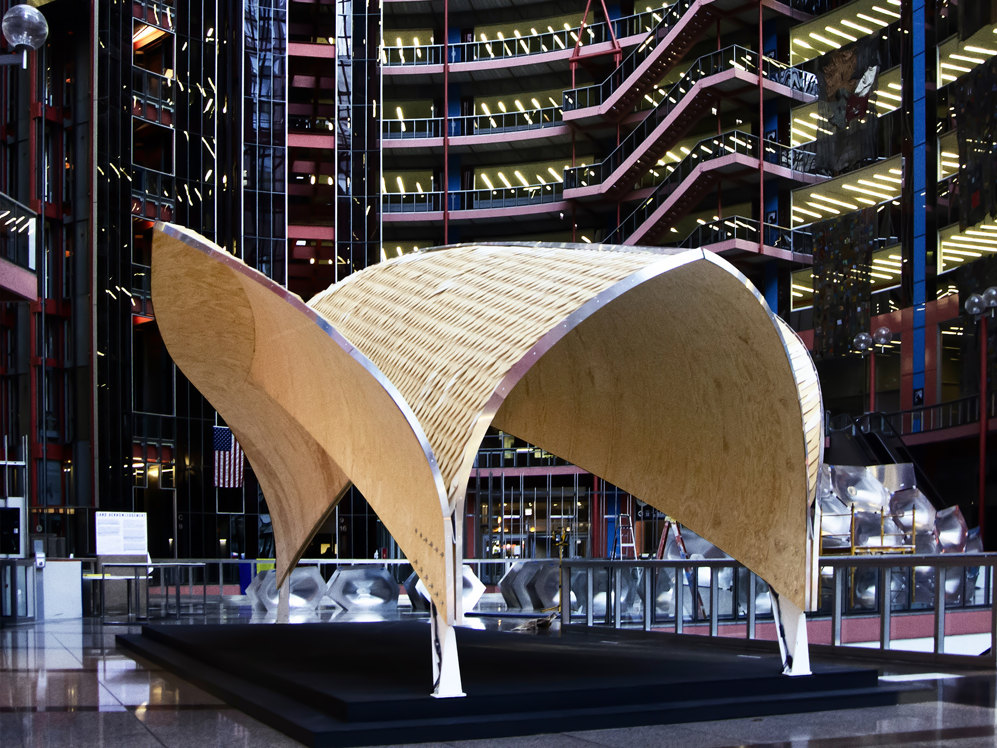
The Hygroshell is a self-shaping building system for deploying lightweight, curved surface structures made from timber. The system uses the inherent hygromorphic properties of wood which naturally shrinks through drying. This anisotropic shape change is embedded into large-scale bilayer sheets – produced, machined, and shingle clad in a flat state with their later curved shape and connection detailing physically programmed within the material build-ups. When placed on-site, these sheets actuate through air drying to a final curved and interlocked geometry.
Geometrically the structure is integratively designed from variable single curved surfaces using key material parameters (end grain angle and moisture content change) within a material stock, in relation to both the self-shaping and the final structural configuration. Each surface is modeled in the curved state using a board specific algorithmic calculation of curvature potential in parallel to a flat fabrication model.

All required boards of the demonstrator were directly sourced from a local sawmill, composing a building system capable of covering an area of 40m2 and span 9.5m, by only containing 2.6cbm of spruce wood. Due to the natural variation in moisture content and grain angle of the raw material, all boards had to be sampled and sorted after cutting. As the board-specific grain angle correlates with hygroscopic expansion and curvature potential, the stock data was fed into a computational model that carefully distributed the boards to achieve the designed curvature gradient.
The base elements of the building system are the bilayer wood plates, composed of a 4mm ‘restrictive’ ply veneer layer and a 20mm ‘active’ spruce wood layer. After lamination the bilayer surface is immediately machined on the worktable in the flat position using a 7-axis milling setup. The connections along the curved wing to wing intersections use an elongated finger joint with sheer blocks in each finger to compensate for tolerances in the lateral direction. The geometry of the curved connection is calculated from the 3D, curved geometry and translated to the flat geometry, considering the change in angle during shrinkage.
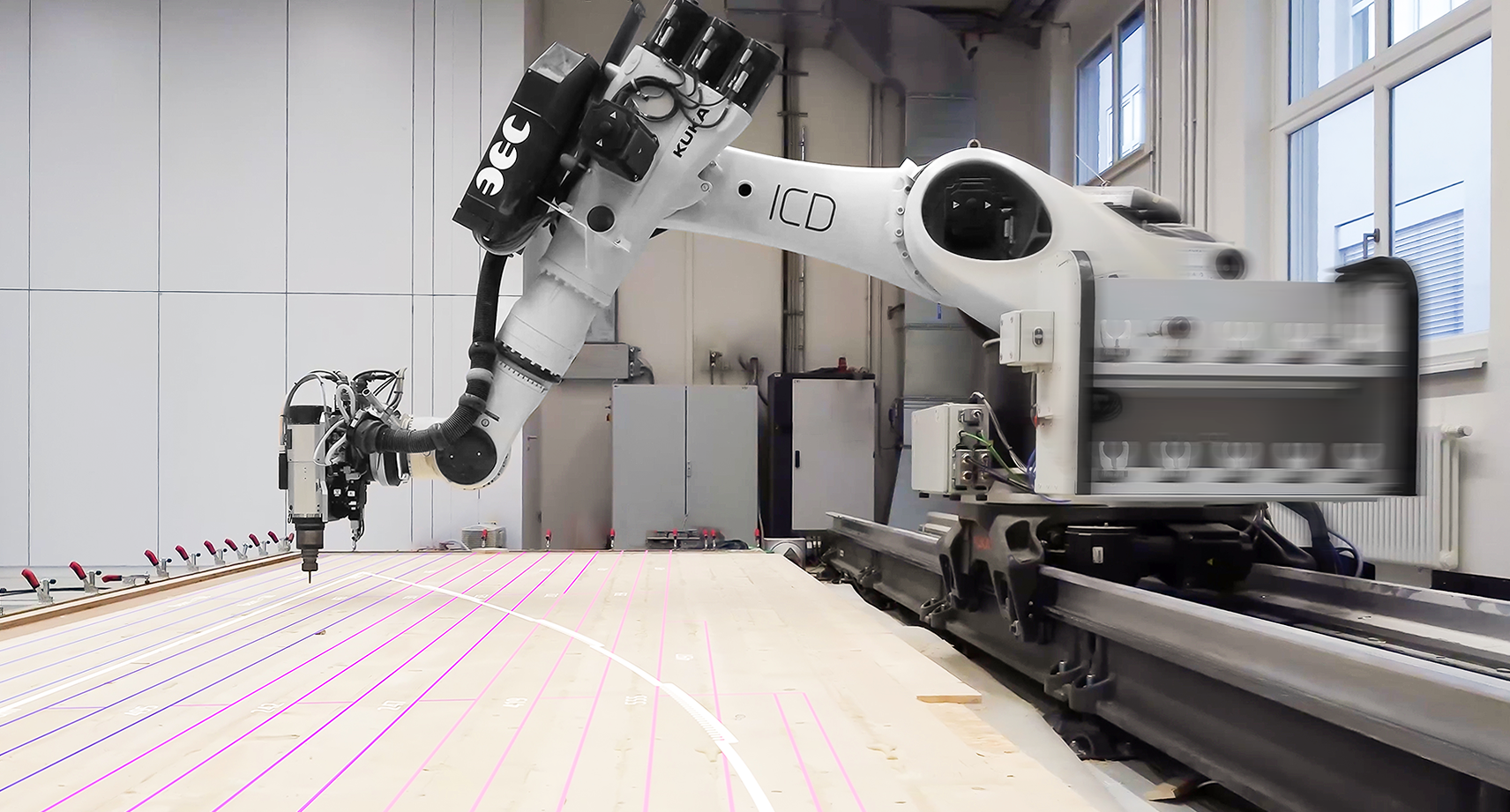
7-axis robotic milling setup, ©itech/icd/itke university of stuttgart
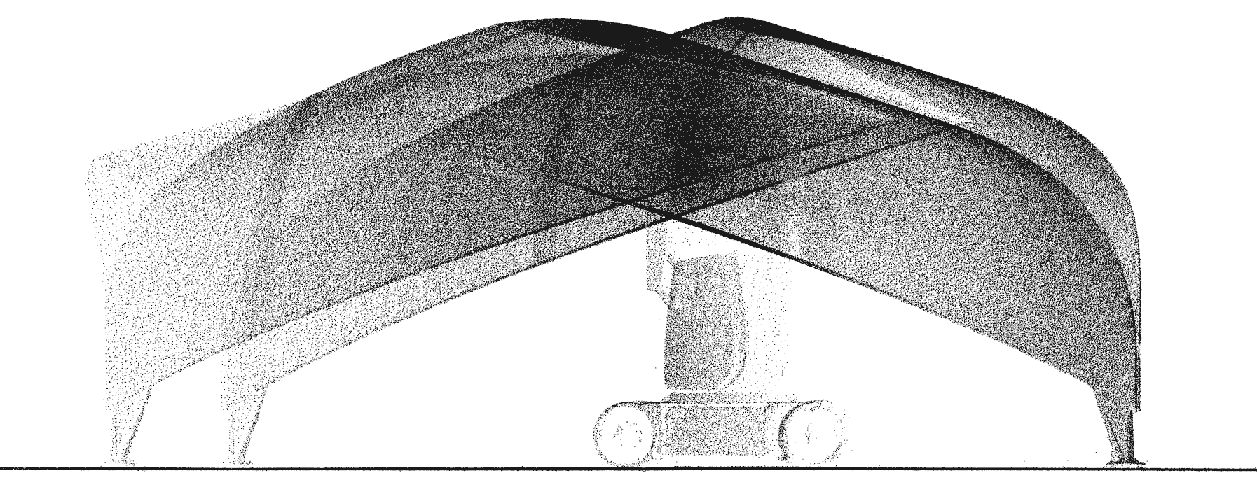
pointcloud scan,
©itech/icd/itke university of stuttgart
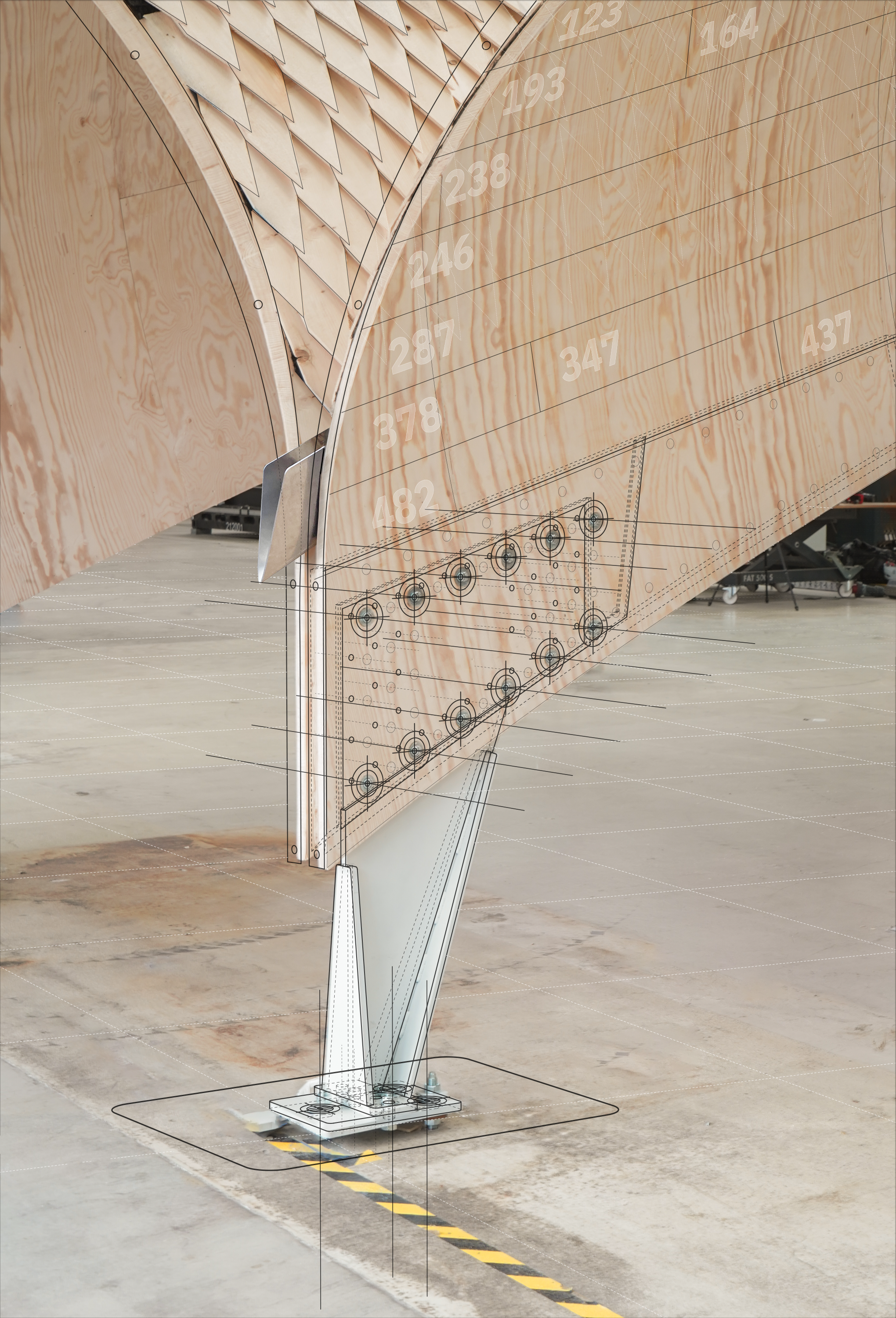
footings detail
©itech/icd/itke university of stuttgart
![]() ©itech/icd/itke university of stuttgart
©itech/icd/itke university of stuttgart
![]() ©itech/icd/itke university of stuttgart
©itech/icd/itke university of stuttgart
 ©itech/icd/itke university of stuttgart
 ©itech/icd/itke university of stuttgart